Motor Control Circuit Diagram With Plc Pdf
Plc programming for 3 motors control in ladder logic Control motor diagram reverse forward circuits plc electric ladder wiring logic programming circuit stop phase digital switch chapter if simulation Plc is ignoring inputs (only sometimes). kinco cpu506. help me solve
PLC PROGRAMMING,PLC LADDER DIAGRAM, PLC SIMULATION,AND PLC TRAINING
Plc wiring diagram please kinco machine Basics of plc programming instrumentation tools Plc motor control dc using diagram direction ladder logo connect soft
Wiring vfd motor control circuit diagram
Vfd plc hmi instrumentationtools driveVfd plc instrumentationtools logic connections controller Programmable logic controller (plc) questions and answersPlc motor logic programmable overload instrumentationtools scada.
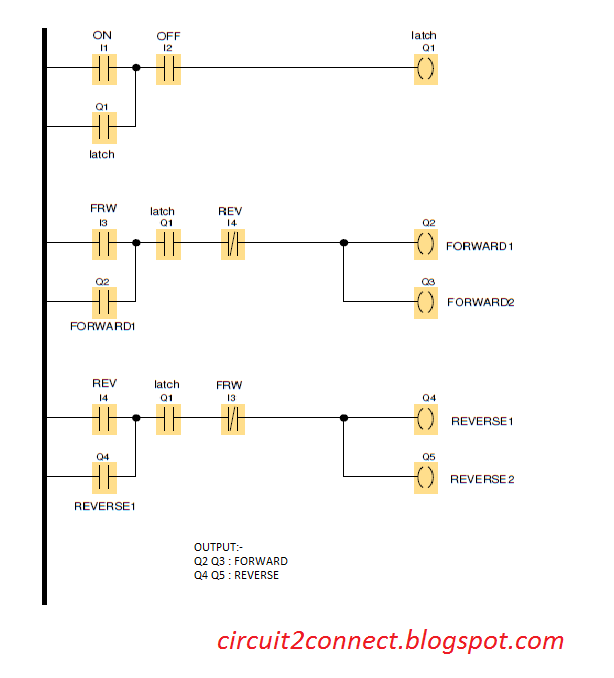
Plc programming,plc ladder diagram, plc simulation,and plc trainingSingle phase induction motor direction control using plc (v3) Direction control of dc motor using plcWiring diagram plc program.

Electrical electronics robotics: plc
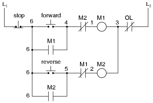
Plc logic programmable circuit programming ladder controllers control digital basics diagram controller terminal common motor output input devices training panelMotor starter diagram wiring electrical phase plc control basic program three circuit ac engineering overload pump portal line stop relay Motor control circuit stepper driver schematics circuits general gr next steppingElectrical wiring diagram forward reverse motor control and power.
Plc control ladder logic programmingForward reverse wiring diagram electrical motor control plc circuit power phase connection mitsubishi eng using elect world1 engineering ladder industrial Motor control circuit page 13 : automation circuits :: next.grControl motor circuit lm317 diagram ic circuits unit based gr next regulator diodes following show.

Motor control circuit page 15 : automation circuits :: next.gr
Plc circuit ladder electrical motor control relay phase robotics electronics program above threePlc motor phase circuit single induction control diagram connection using direction connect v3 shown below Motor control circuit diagram taking into account bearing in mind plc.
.

PLC is ignoring inputs (only sometimes). Kinco CPU506. Help me solve

Programmable Logic Controller (PLC) Questions and Answers - 22

Wiring Vfd Motor Control Circuit Diagram - Plc Wiring Vfd Wiring Skills

motor control circuit Page 13 : Automation Circuits :: Next.gr
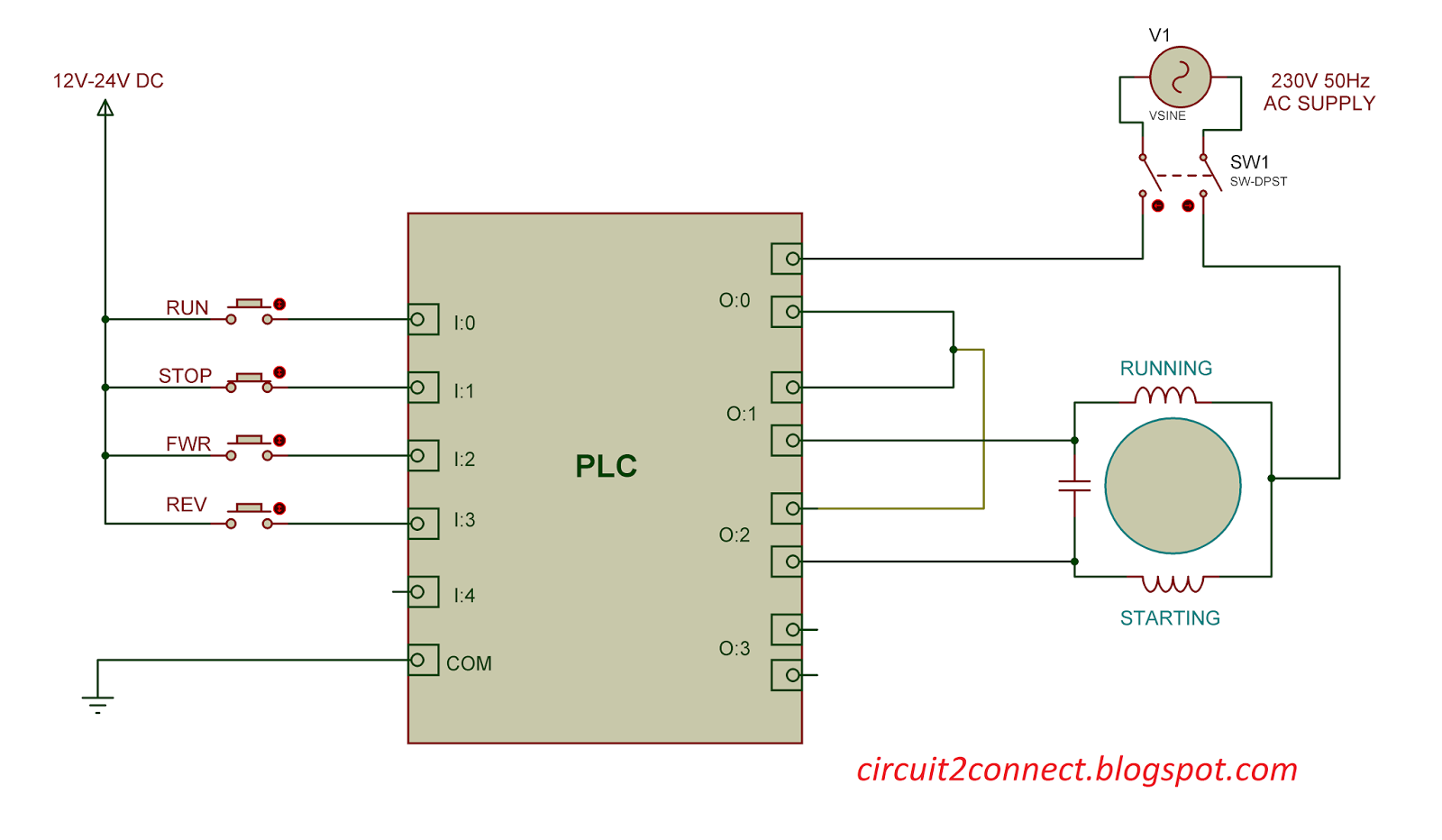
Single Phase Induction Motor Direction Control Using PLC (v3) - Circuit

motor control circuit Page 15 : Automation Circuits :: Next.gr
PLC PROGRAMMING,PLC LADDER DIAGRAM, PLC SIMULATION,AND PLC TRAINING

Basics of PLC Programming Instrumentation Tools

Electrical Wiring Diagram Forward Reverse Motor Control and Power