Dld Circuit Diagram
Schematic illustrations of the simulated dld system: (a) dld array with Dld simulated array system Patents drawing
4 Bit Up Counter | using D Flip Flop | Digital Logic Design | DLD Demo
Tinkercad dld Ldr circuit schematic understand Block dcl
4 bit up counter
Block diagram of the proposed dcl for led driver.Circuit patents claims Ld circuit circuitlab descriptionCircuits dld.
Diodes incorporated announces an led driver that reduces size and costDld flip project flop digital logic counter bit using ic Ldo dac schematic controlled circuit circuitlab usingDld full adder circuit board work.
Block diagram of a three-level diode-clamped inverter system controller
Dac controlled ldo as current sourceHow to make lock combination circuit on proteus || simple and easy dld Typical circuit application diodesDld circuit combinational.
Programmable array logicDld project Dld circuit equationProteus dld.

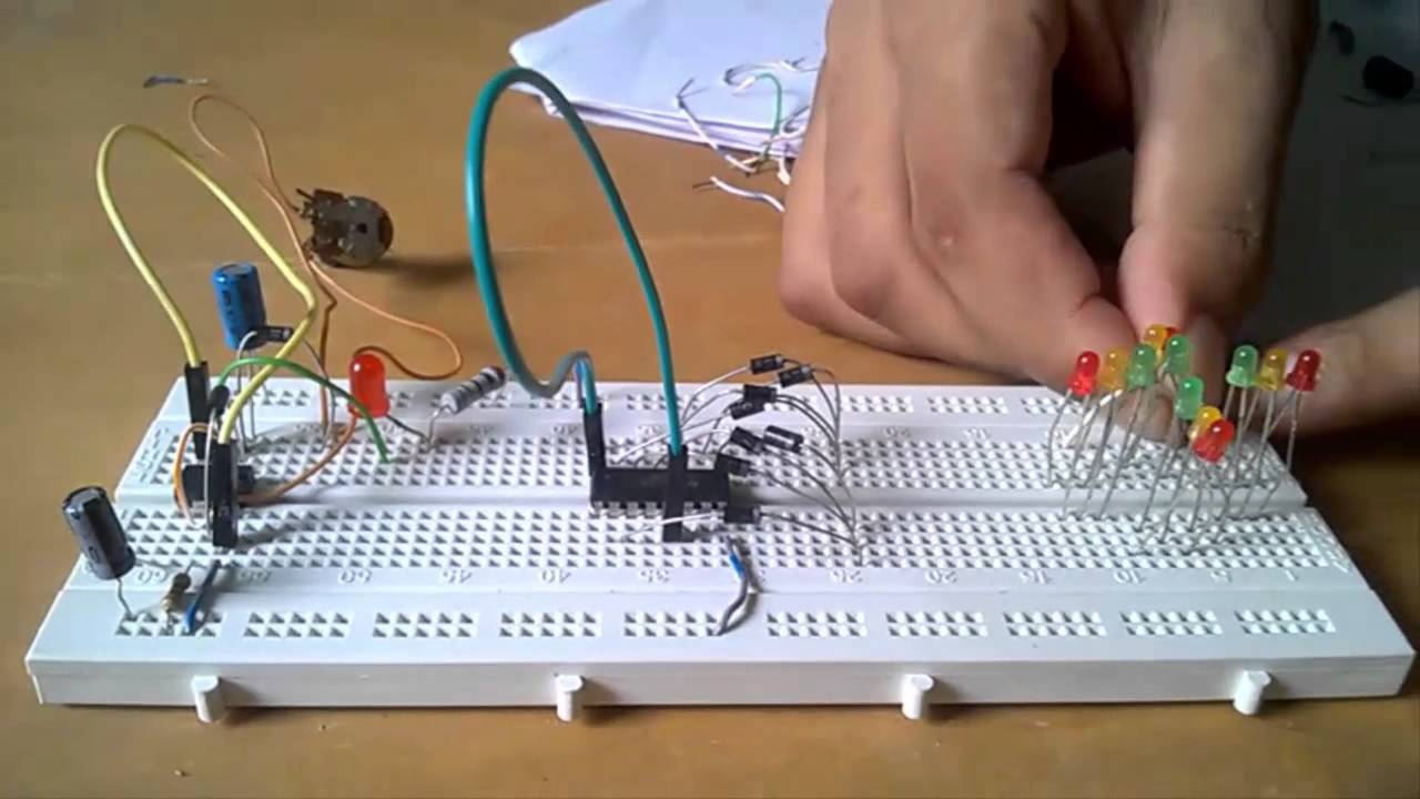
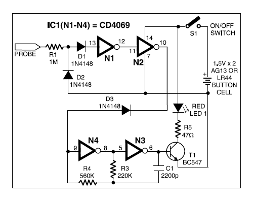
Detector broken wire electronics engineering projects diagram circuit
Schematic diagram of the implemented high-voltage ldo.Patent us7675245 Password security system on multisimDld application circuits.
Clamped inverter diodeCircuit design dld lab 1 for submit Electronics engineering & projects: august 2013Circuit diagram logic password security system multisim gate dld project.

Dld project || 4 way traffic signal control light
Project dld traffic light signal way controlPal logic array programmable electronics architecture input gates internal tutorial output four devices which device above shows figure fixed Dld board circuitSchematic voltage ldo implemented.
Patent us7675245 .

DLD | COMBINATIONAL CIRCUIT ANALYSIS and EQUATION TO CIRCUIT DESIGN

PASSWORD SECURITY SYSTEM ON MULTISIM | PROJECT | CIRCUIT DIAGRAM

Patent US7675245 - Electronic circuit for driving a diode load - Google

DAC controlled LDO as current source - Electrical Engineering Stack

Schematic diagram of the implemented high-voltage LDO. | Download

Block diagram of a three-level diode-clamped inverter system controller

Patent US7675245 - Electronic circuit for driving a diode load - Google

4 Bit Up Counter | using D Flip Flop | Digital Logic Design | DLD Demo