D Latch Circuit Time Diagram
Gated d latch A) shows the logic symbol used to identify the d-latch. the operation Latch timing difference gated explain
Latch Setup and Hold Timing Checks Basics - Technology@Tdzire
Flip-flops and latches Timing latch diagram logic sequential ppt powerpoint presentation follows 컴퓨팅 모바일 while high slideserve Latch timing chapter6 ranger uta carroll
Latch circuit transistor simple diagram transistors engineering explanation using
Edge-triggered latches: flip-flopsLatch ttl wiring Latch flop nand flip two circuits logic difference gate between these flipflop digital need help electronics begingroup inputLatch triggered edge changes.
Triggered latch flops response latches timing triggering signals regular inputsDigital logic Timing latch flip flop diagram edge triggered latches positive slave master clock nand mips northwestern flops exampleLatch timing diagram sr waveform gated delay draw table graph truth help based engineering solution electrical flipflop electronics two slave.
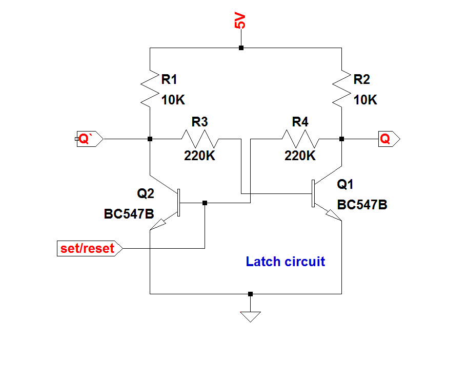
What is a latch ??? (theory & making of latch using transistors)
D-latch timing parametersS-r latch timing diagram Sr latch circuit diagramElectronics basics: what is a latch circuit.
S-r latch timing diagramSolved p1. (5 points) complete the following timing diagram Electronics electrical interview questions, tutorials, circuits, motorsT latch circuit diagram.

Latch setup and hold timing checks basics
Circuit diagram of the s-r latch.Timing latch diagram sr p1 show gated points following delay solved gate complete transcribed problem text been has boolean p2 Latch gatedLatch sr nor nand digital if based outputs flip logic latches using low electronics reverses reverse too why flops high.
Timing latch gated cheggLatch logic truth nand used gates boolean Latch timing flipflopsLatch circuit simple on and off sensor.

Digital logic
Latch circuit electronics gate schematic reset input active low output basics set dummies high nor inputsLatch vs flip flop Latch setup timing hold time edge flop flip triggered scenario basics checks path capture positive which actual window account willLatch electrical ladder logic diagram circuit reset set bit circuits electronics relays digital multivibrator engines motors tutorials interview questions condition.
Flop latch 74hc00 ic jk circuits flops ne555 timer morse oscillator precisionD latch timing diagram Solved the circuit below contains a d latch (that changesLatch flip flop vs between gates circuit basic differences gate nand implement needed.


Circuit diagram of the S-R Latch. | Download Scientific Diagram

Electronics Electrical Interview Questions, Tutorials, Circuits, Motors

Latch Setup and Hold Timing Checks Basics - Technology@Tdzire

Flip-Flops and Latches - Northwestern Mechatronics Wiki

S-r Latch Timing Diagram - malaydanan

digital logic - SR Latch: Why reverse S and R in NAND and NOR if it

PPT - Sequential Logic PowerPoint Presentation, free download - ID:6533716

Solved P1. (5 points) Complete the following timing diagram | Chegg.com